
Download the Starshade Challenge Template
Summary
Undergraduates are invited to form groups to compete in a NASA-sponsored challenge to design a starshade for an earth-based telescope. The challenge will focus on the following:
- a conceptual design of the starshade using ‘first principles’ & fundamental structural analysis to ensure critical requirements are met, and
- building a 1:100 scale model (or larger) of the design using materials that could be scaled up on a NASA mission
Submissions will be evaluated by a NASA-led committee and winners will be selected. Modest support to build a scale model and awards will be issued to participating university teams, as listed below. This challenge could be incorporated as part of a Senior Capstone Design Course, research credits, or a for-credit design course.
Concept generation
Students are tasked with performing a conceptual design of the starshade using ‘first principles’ & basic structural analysis to ensure key requirements are met.
Sign-up period: Before September 5, 2023
Timeline: September 5, 2023 – December 15, 2023
Submission deadline: December 15, 2023
Submission: Undergraduate individuals or groups are asked to submit a detailed design of a starshade that could be built on earth and deployed in space that meets the provided criteria, as defined in the technical specifications section. This challenge could be incorporated as part of a Senior Capstone Design Course, research credits, or a for-credit design course. Undergraduates are strongly encouraged to form teams from within their local department(s) or universities. It is strongly recommended that a faculty member is selected to provide advice and guidance and to be a local sponsor for submission. The faculty member may assist but may not solve the problem for the group.
Submission materials should include the following:
- General form – including contact and university information
- A short, general audience description of the motivation behind your design. This section is designed to be shared with the general public and should be aimed at high school students with no physics/engineering background.
- Computer-Aided Design (CAD) drawings of a starshade in both the stowed (inside rocket fairing) and deployed (in space) configurations. 2-D and or 3-D drawings should include dimensions and material information, which should be included in the Starshade Challenge Template. Teams may use as many CAD drawings and figures as needed to explain their design correctly.Teams may also use as many figures as needed to properly explain their design. Sketch details should discuss dimensions and material information which should be included in the StarShade Challenge Template.
- The Starshade Challenge Template: including a checklist showing which mission requirements are in compliance (discussed below). The following mission requirements are considered essential to a successful submission: 1, 2, 3, 5, 6, and 9. Additional requirements are optional, but submissions that meet more of the stated requirements will be given higher scores. Note: It is understood that meeting all requirements at once is very challenging, and successful submissions need not meet all criteria.
- Requirements’ discussion and Analysis: Provide a detailed discussion of how the design meets requirements 1, 2, 3, 5, 6, and 9 and any of the optional requirements. This section is included in the Starshade Challenge Template. The discussion must include Free Body Diagrams of forces and corresponding analytical calculations for loads and stiffnesses of the major portions of the structure. Free Body Diagrams and analytical calculations are required, and step-by-step work must be shown using Mathcad Prime (highly recommended), engineering paper, or equivalent, i.e., an Excel spreadsheet where formulas cannot be seen is not allowed. Computer Aided Engineering software, such as finite element analysis (FEA), is not permitted in calculations. Entries that do not include hand analysis or that use or are suspected of using FEA will be automatically disqualified. The structural analysis shall be delivered in PDF format as part of the Starshade Challenge Template. A sample calculation is here.
- Documentation of a 1:100 scale model of the proposed design. The scale model should be of the deployed starshade and use materials and structures which can scale with size.
- All submitted documents are to be put together in a single document based on the Starshade Challenge Template that includes your executive summary, description and overview of your design work, rendering, analysis report, explanation of compliance to requirements, and requirements checklist, all in one single file document in PDF format.
- Extra credit:
- Create a student created 5-10 minute YouTube video with a presentation of your design and analysis with an emphasis on compliance with the requirements using a maximum of 10 slides.
- Build a 2:100 or 3:100 scale starshade and get bonus points
Financial support: The first twenty university teams to register and meet with staff will be offered an honorarium of $1,000 for the material costs to build the scale model. Funds will be disbursed to the sponsoring department at the recipient’s university.
Teams can be updated at any time and are encouraged to form up to 20 students. A faculty sponsor is required to help facilitate communication with the group.
Grading Criteria
Will be based as follows:
- CAD Drawings: 20%
- Free Body Diagrams and Hand Calculations: 25%
- Project Report / Document: 20%
- Construction of Starshade Model: 35%
- Extra Credit:
- YouTube video 10%
- 2:100 Starshade model 20%
- 3:100 Starshade model 30%
- Models using a 48-petal Starshade 10%
- It is anticipated that the winning entries will need to excel in all of the above categories
- Entry must include all of the above 1 through 4 items, e.g., focusing on the starshade construction and skipping the project documentation or other portion is not allowed.
Recognition:
- Recognition takes the form of a student travel fund award and will be:
- $10,000 for first place
- $6,000 for second place, and
- $4,000 for third place.
*Awards are intended to be used to support student travel and research.
Technical Background
Starshades can cast deep shadows of the target star if they are properly shaped to manage diffraction. The optimal shape has a central dark region surrounded by tapered petals. Originally it was thought that only telescope/starshade combinations in outer space could achieve adequate performance. But with the 30 m class telescopes (GMT, TMT, and ELT) currently under construction on Earth and high-performance single conjugate adaptive optics (SCAO) at visible wavelengths, it will be feasible to make these observations from the ground.
These large telescopes enable the Hybrid Observatory concept, with a starshade orbiting in space and a telescope on the ground. The starshade must maneuver to be precisely on the line from target star to the telescope, matching both position and velocity, and must accelerate to stay on this line as the Earth (and observatory) rotates. If such a system could be built, it could image a solar system in 1 minute at a distance of 5 parsecs and obtain planetary spectra with oxygen and water in 1 hour.
A spectrum like the Earth’s would provide a strong indication that life is present on the planet being observed. Such a hybrid observatory could have an observing speed 1000x greater than a 6 m space telescope, as well as produce images with 6x better angular resolution. The orbit choice is a solved problem: a high ellipse with an apogee of at least 170,000 km, so the starshade can match velocity with the observatory as the Earth rotates.
The complete starshade is a spacecraft with all the systems a typical spacecraft requires. A key challenge for a cost-effective starshade system is caused by the rocket equation which governs two things: how long the starshade spacecraft can match the acceleration of the observatory and how many times its orbit can be adjusted to enable observations of different target stars. The first is managed with chemical propulsion.
The second is managed with high Isp (specific impulse) solar electric propulsion. In both cases the scientific yield is roughly proportional to the achievable velocity changes. The upshot is that a low starshade structural mass is critical for a cost-effective mission. NASA hopes that the GrabCAD community can help develop innovative structural concepts to reduce the overall mass of the starshade structure.
Starshade designs were developed at JPL for space-based telescopes like the Nancy Grace Roman Space Telescope and the proposed HabEx mission. Details on the design can be found on the websites listed later in the challenge description.

There is little doubt that the 50 m diameter starshade required for a space telescope could be built and launched for a 6 m class space telescope. However, extrapolating the current 50 m diameter starshade design to a 100 m scale for use with a 30 m ground telescope showed that the mass and volume would be too high for even a Falcon Heavy rocket if adequate propellant for maneuvering was added. We therefore seek alternate concepts. Such concepts include radical light weighting of the JPL concept; a deployable umbrella with petals; a rigidizable inflatable structure; and an ultralight truss, perhaps assembled in space by robots or astronauts.
We are inspired by the Eiffel Tower, which is a third-order hierarchical structure, in which truss elements are themselves trusses, etc. Much work has been done on in-space assembly as well, and indeed there is a new National Strategy for it that could lead to implementation.
The goal of this challenge is to develop an innovative low-mass starshade structure that could meet the mass, shape, strength, and stiffness requirements. Solvers can consider one of these categories or a hybrid design:
- Ultralight version of the current JPL HabEx concept
- Umbrella with petals
- Rigidizable inflated structure
- Truss-based structures
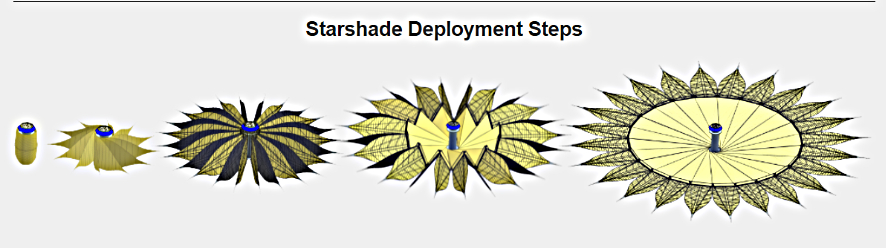
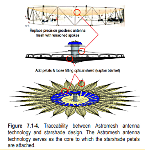
In addition to being very lightweight, the ideal starshade design should be self-deployable (although we are interested in other options) and allow for compact packaging. NASA is looking for innovative packaging and deployment methods that can reliably deploy the starshade system after being placed in Earth orbit. We seek ideas to complement our studies currently in progress, hence the challenge. Our highest priority is low mass. See Figure 7.1-4 for example designs from the HabEx final report.
Requirements
- Mass: The starshade structural mass including opaque membranes shall be less than 1,000 kg. (Since the estimated mission cost is roughly proportional to this mass.) This mass target does not include the central hub, spacecraft bus, propulsion system, solar arrays, and power supply.
- Shadow/sunlight: The starshade casts a shadow of the star based on the shape of a flat surface. To detect light from extrasolar planets, it is critical that reflected sunlight does not saturate the detectors. Reinforcing structures may project above or below this flat surface, with some restrictions. In use, the starshade plane may be tilted up to 30 degrees from being perpendicular to the line of sight to the telescope. The line perpendicular to the starshade plane may also be oriented at angles from the Sun ranging from 40 to 80 degrees, so the Sun is only 10 degrees above the starshade plane. In all these cases, during observations, no sunlight may strike any part that is visible to the telescope, except the sharp edges. (This is to ensure the widest range of useful angles between the Sun and the target star.) See associated graphic. To construct the excluded volume above the starshade, construct a cone with a vertex on the boundary, open upwards, and half-angle of 30 degrees, and move it around the boundary of the starshade. To construct the excluded volume below the starshade, do the same but open downwards, with a vertex half angle of 80 degrees.
- Petal edges´ sharpness: To minimize sunlight scattered towards the telescope, the starshade edges must be sharp, thinner than paper. Starshade also needs to include an optical tip as shown in figure below. Therefore, the packaging and deployment or assembly process must protect all parts from damage.

- Acceleration/ load factors: When fully deployed, the starshade shall withstand accelerations of 0.03 g’s in the axial (out of plane) and lateral (in plane) directions (phase I requirement). Starshade must recover its zero-g shape within tolerances within 10 seconds or less (phase II requirement). This is to match the observatory acceleration of up to 0.003 g, using pulses from the rocket. The rocket thrust to maintain alignment during observation will be pulsed with a roughly 1-minute period and a duty cycle <10%, because the jets themselves are bright enough to interfere with observations. Hence, rapid recovery from transient acceleration is required. Note that this requirement also implies that the starshade could be constructed or assembled in low Earth orbit if desired and could withstand the force of a small booster to reach the high orbit needed for observations.
- Spacecraft bus volume: The deployed starshade shall accommodate an empty cylinder 2 m in diameter in the center, open on both ends. This is reserved for the spacecraft bus and propellant tanks. The rocket jets should be assumed to be on both ends of this tube and oriented to avoid direct impingement on the starshade itself. Normally they will be fired in balanced pairs to avoid undesired torques, but they can also be used to produce any necessary torques to re-orient the starshade. Protecting the starshade material from the jets is outside the scope of this study. See associated graphic.
- Mission duration: The starshade structure shall support a mission duration of 3 years (prime mission) with a preferred goal of 4 x 3 years with 3 refueling visits. This requirement means that an inflatable system must be rigidized or have a very good leak control, given the expected number of micrometeoroid impacts based on statistical analysis.
- Central disc Size: The starshade shall have a central disk of 25 m radius.
- Number of Petals: The starshade shall have at least 24 petals, each being 25 m long (See basic HabEx design) with 48 petals being the most desired and optimal configuration.
- Petals deflections and edge shape tolerances / Minimum deployed frequency: In zero gravity during observations, the starshade shall have an edge shape tolerance of 5 mm with petal position tolerance / in plane deflection of 5 cm. This is looser than for smaller telescopes and smaller starshades. Petals are allowed to move out of plane by 1 meter as long as the shadow has the right shape within tolerances, and the sun does not illuminate parts seen by the telescope.
- Stowed volume inside rocket fairing: The packaged starshade (including central cylinder) should fit into a cylindrical package that is 14 m long by 4.5 m in diameter. (This is approximate and is based on the extended fairing static envelope specified in figure 12-10 of the Falcon Payload Users Guide. If targeting a different Launch Vehicle or performing in-space assembly, provide your assumptions.)
- Launch Loads: When in a packaged configuration, the starshade must be capable of surviving launch loads (high levels of vibration/acoustics could damage some brittle materials) as specified in Falcon Heavy Payload planners guide Section 4.3.
- Deployment: Starshade shall be able to deploy without having any of its components breaking, getting stuck or snagged and in less than 5 hours. Deployment system employed shall be able to provide positive a Force / Torque Margin ((FM = Favailable /Fresistive – 1>0)
Analysis
Analysis is a key component of the challenge. The main goals of the analysis are to:
- Have students practice applying ‘first principles’ when trying to tackle a complex engineering problem. This allows them to gain a better understanding of the physics involved in the problem while applying the fundamentals learned in school.
- Reinforce the concept that when designing something, the design is driven by the requirements. During the initial design phases, hand analysis is the most efficient way to check the design against the given set of requirements.
- Once design has converged into a good concept, advanced tools such as finite element analysis (FEA) and other software packages may be used on Phase II. The goal is to prevent students from focusing exclusively on software CAE packages as this leads to a quick erosion of their analytical skills before they have learned the fundamentals.
Phase I Analysis: Teams are to provide documentation which explains the structure and materials in detail sufficient to engineer the starshade. The overall goal of phase I is to propose interesting and novel structures that are structurally sound based on structural analysis hand calculations using a ´First Principles’ approach. After learning the fundamentals of mechanics this is your chance to apply what you have learned in school to a real-life NASA engineering problem.
Phase II Analysis: Now that you have a good understanding of the physics involved in the problem and have a sound preliminary design, it is time to enhance and optimize your design using Computer Aided Engineering (CAE) tools such as Finite Element Analysis (FEA) to solve for loads, stiffness, buckling, stresses and fundamental frequencies of the components of your starshade concept as needed, and to show compliance with all the requirements.
The overall analysis requirements are as follows:
- Performing Structural analysis as part of your design process using hand calculations is strictly required. Phase I teams must show a Free Body diagram with forces involved and use formulas from Roark & Young, Timoshenko, Shigley, and other structural analysis references to show how you solve for loads, stiffness, buckling, stresses and fundamental frequencies of the components of your starshade concept as needed, to show compliance with the requirements. Note: A full Finite Element Model exceeds the scope of Phase I and is not required, but if you would like to and you have the time, you may create one but only after hand structural analysis has been completed. Using only Finite Element analysis (or an insufficient hand analysis followed by FEA) will not be accepted and lead to the disqualification of the entry. For phase II, use Computer Aided Engineering (CAE) packages to enhance and optimize your starshade design, the computation of loads, stresses, deployed frequencies, etc. is strongly recommended.
- International system of units (kg, m, sec, K) shall be used in analysis calculations. Angles shall be reported in degrees.
- The following coordinate system shall be used when performing analysis and calculations.

- Use Load factors of 0.03 in the X, Y (lateral) and Z axial directions (corresponding to the 0.03 g’s axial and lateral acceleration case).
- Minimum deployed frequency/stiffness: design the starshade with axial, lateral, bending, and torsional stiffnesses such that during observations, the maximum in-plane petal deflection is +/- 5 cm and the maximum allowed out-of-plane petal deflection is +/- 1 m. After any disturbances, starshade shall recover its zero-g shape within tolerances in 10 seconds or less. This analysis is stressed in Phase II.
- Factors of safety of 1.25 (yield) and 1.4 (ultimate) for metallic structures and 1.4 (ultimate) for composite/bonded structures shall be applied to the limit loads to determine the yield and ultimate design loads and show positive margins of safety on strength.

Example
- Axial limit load factor nz = 0.03
- Limit load (axial) = 1000 kg * 0.03g’s = 294.2 N
- Design ultimate Load (axial) = 1.4* 294.2 = 411.9 N
- Margin of Safety on ultimate axial loads = Allowable Load (or stress) / Design Load (or stress)-1 > 0to satisfy design criteria.
- For kinematic deployments consider showing your kinematic analysis as well as forces involved during the deployment.
- Compute your deployment Force / Torque margin using the following equation:

where Favailable are the forces helping the deployment and Fresistive are the forces opposing it, and FM / TM required to be positive throughout the entire deployment.
For analysis requirements that must be met on each of the phases please refer to Phase I and Phase II submission requirements section.
Note: It is recognized that there are many more requirements for a flight system, such as shape accuracy for the shadow, thermal stability, opacity of the starshade after micrometeoroid impacts, and sun glints from the edges. Here we concentrate primarily on the mechanical concept and emphasize its mass.
For this contest, a graphic showing the HabEx starshade design has been provided as a starting point. When scaled up to a 100 m diameter, the HabEx design will not meet the mass requirements for the Hybrid mission concept so an alternate design must be considered. One design category is an improvement of the HabEx design, which already includes concepts for packaging and deployment, and edge protection. Please refer to the links provided at the end of this document for mor information regarding the HabEx design.
Ideas that should be excluded:
- Avoid concepts that require extensive human or robotic support for assembly and/or deployment since this would greatly increase the cost of the mission.
- Avoid concepts that are extremely complex as this adversely impacts fabrication, reliability, and increases mission risk.
- Avoid concepts that require technologies that have a very low technology readiness level since this greatly increases development risks.
Re-use of existing inventions is highly desirable. Extensive work has already been done on hierarchical materials, inflatable structures, coilable booms, artificial intelligence, and genetic algorithms to remove unnecessary mass. Many studies have been done on in-space assembly and construction, but few structures have been required to tolerate significant acceleration after completion.
Similarly, the natural world has remarkable examples of ultralight structures, ranging from hollow bird and dinosaur bones, dragonfly wings, to feathers, to composite materials like wood and bamboo. Engineered ultralight systems have been developed for human-powered aircraft, for radio antennas, and for racing yacht masts. Self-erecting cranes are segmented trusses engineered for high strength and low mass. In summary: A year in the laboratory can save a week on the Internet.
Eligibility
In order to be eligible for a prize, solutions must originate from students currently registered at an educational institution (university, community college, etc.) located in the United States or its territories (Puerto Rico, etc.) and pursuing a degree in physics, engineering, astrophysics, or other related fields.
Intellectual Property
The Government is seeking a full government purpose usage license for further development of a starshade design to support the HOEE mission concept. It is hoped that the winning concepts can be included in HOEE study presentations.
Grading Scale
The following scale will be used to evaluate entries in the competition during phases I & II.
- Mass requirement:10%
- Stiffness requirement: 20 %
- Quality of CAD and simulation:20%
- Quality and accuracy of analysis and hand calculations:30%
- Other requirements (including optical requirement, size requirement, etc): 10%
- Report:10%
Design Notes from the challenge owner
It is common to assume that to make something stronger and stiffer, we should increase its mass. But this intuition fails when the item being strengthened is its own mass load. We expect that ingenuity is required in suitable geometric shapes that are naturally strong and stiff, and not subject to Euler buckling. It is hoped that a winning concept will be sufficiently robust that deployment on the ground does not require perfect g-negation (gravity compensation) systems.
We note that ultralight space structures are rarely stiff enough to meet our requirements, and our structure needs substantial thickness. The lowest mode frequency of an unsupported flat bar is about f = c(T/L 2) where c is the speed of sound, equal to (E/ρ) 1/2, where E is the Young’s modulus and ρ is the density. T is the thickness, and L is the length. If c=5000 m/s (e.g. aluminum) and T is 0.3 m and L is 71 m, then f is about 0.3 Hz.
We need a way to remove most of the material, while maintaining a high specific stiffness, and increase the damping, so that vibrations die out quickly. Also, deformation under acceleration scales as a(m/k) where a is the acceleration, m is a mass, and k is the stiffness. A mode frequency for a mass on a spring is (1/2 π)(k/m) 1/2 so the deformation under acceleration is of order a/(2π f) 2. If a = 0.03 g, f = 0.3 Hz, then the deformation is only 8 cm. Our structure must be very stiff, more like a bridge than a solar sail. Note that 0.3 Hz is not a requirement, only an example.
For information on starshades and the hybrid mission concepts see:
- HabEx Final report:https://www.jpl.nasa.gov/habex/pdf/HabEx-Final-Report-Public-Release-LINKED-0924.pdf
- NIAC summary:
https://www.nasa.gov/directorates/spacetech/niac/2022/Hybrid_Observatory_for_Earth_like_Exoplanets/ - Starshade tutorial – Doug Lisman:
https://www.jpl.nasa.gov/habex/documents/Aug2016/Lisman-Starshade.pdf - Starshade tutorial – Steve Warwick:
https://www.jpl.nasa.gov/habex/documents/Aug2016/Warwick-NG-design-briefing-to-HabExSTDT.pptx - In-space assembly strategy:https://www.whitehouse.gov/wp-content/uploads/2022/04/04-2022-ISAM-National-Strategy-Final.pdf
- Falcon Users Guide:https://www.spacex.com/media/falcon-users-guide-2021-09.pdf
- ExEP web sitehttps://exoplanets.nasa.gov/exep/starshadedocuments
https://exoplanets.nasa.gov/exep/technology/starshade/ - Exoplanet Strategy reporthttps://www.nap.edu/read/25187
- SPIE JATIS special issue:https://www.spiedigitallibrary.org/journals/Journal-of-Astronomical-Telescopes-Instruments-and-Systems/volume-7/issue-02/021201/Special-Section-on-Starshades-Overview-and-Dialogue/10.1117/1.JATIS.7.2.021201.full?SSO=1
- ORCAS report on adaptive optics:
https://asd.gsfc.nasa.gov/orcas/docs/ORCAS_AS3_Study_HQ_Report_Origin_Public_Version.pdf - Many books and papers are published on metamaterials materials. For example this article by Roderic Lakes, at U Wisc:
http://silver.neep.wisc.edu/~lakes/home.html, and his book “Composites and Metamaterials, July (2020)”.
https://ui.adsabs.harvard.edu/is an interface to articles relevant to astrophysics and includes SPIE journals.
Appendix: Reference text from funded proposal
Hybrid Observatory for Earth-like Exoplanets (HOEE)
Principal Investigator: John Mather (GSFC)
Co-Investigators/Collaborators: Jonathan Arenberg (Northrop Grumman Space Systems), Matt Greenhouse (GSFC), John Grunsfeld (Endless Frontier Associates), Anthony Harness (Princeton), Rudranarayan Mukherjee (JPL), Alejandro Rivera (GSFC), Stuart Shaklan (JPL)
NASA solicitation 80HQTR21NOA01-22NIAC A1
5.3 Starshade Challenge
A small Challenge could produce new and better concepts. College mechanical engineering students have built balsa wood bridges for generations. We have a different challenge: to build a structure that supports itself (at least for student projects) and casts the right shape of shadow, with minimum mass. Scaling a 1000 kg 100 m starshade to a 1 m scale leads to a mass of 1 gram. Scaling down the membrane thickness will have to be omitted; 1/100 of the thickness of 1 mil Mylar is too thin to consider, but if it is used for structural purposes, it could be replaced in the model by threads covering 1% of the area. A higher-level aim is to develop interest and skill in solving ultra-light engineering challenges. Moreover, student/academic involvement involves the aerospace community and the public in raising awareness and contributing to progress on this exciting mission.
After finding a range of promising mechanical concepts, we will explore lightweighting them with hierarchical structures. Hierarchical structures are systems like trusses, in which the major shape is built from elements, which are in turn built from smaller elements.
The Eiffel tower is a classic example, put together from discrete elements. A solid bar has order 0, a truss has order 1, a truss made of sub-trusses is order 2, etc. The Eiffel tower is 3rd order. Each successive order produces a lower average density and effective stiffness and strength, but the stiffness and strength per unit mass can be about the same.
A hierarchical structure can therefore have nearly the same mode frequencies and deflection under acceleration that a lower order system would have. This concept was a cover story for Nature in 1993,9 and is actively being developed in universities to produce metamaterials with e.g. negative thermal expansion coefficients.10 There is a practical limit for low density materials that must survive launch, but a structure fabricated in space would escape that limitation.
Likely materials students could use would include: thread and fishing line for tension members, balsa wood, Styrofoam, foam core board, corrugated cardboard, straws for compression members, and wire for springs. The opaque membrane cannot be scaled down in thickness but can be replaced by threads with the right filling factor.
Aerospace versions could include aerogel, aluminum honeycomb, Astromasts (coiled deployable trusses), bistable tape springs (aka carpenters’ rulers), extending concentric tubes as used for the JWST sunshade, and rigidized inflatables of arbitrary shapes. High order truss structures might be winners, and students might find ingenious ways to design and construct them. Space manufacturing techniques (to be evaluated in a later stage) might produce another level of hierarchy and even lower mass.
Organizations to be invited include aerospace engineers at MIT; Starshade Rendezvous team members led by Prof. Sara Seager at MIT; the Aerospace Engineering school at University of Maryland College Park; and mechanical engineering classes at HBCUs and the Baltimore campus of the University of Maryland (UMBC). The Society of Physics Students of the American Institute of Physics would be a suitable way to reach many schools, as is the American Institute of Aeronautics and Astronautics with its Student Chapters, and the American Society of Mechanical Engineers.
Contact information:
Inquiries should be sent to:
Janessa Slone [email protected]
Project lead at AIP:
Brad Conrad
Director, Society of Physics Students
American Institute of Physics
1 Physics Ellipse
College Park, MD 20740
Phone: 301‐209‐3007 [email protected]